Dirty Electricity (EMC) Research Papers
(I.E. STETZER /GREEN WAVE)
There is a considerable amount of confusion regarding the new Smart Meter also called AMI (Advanced Meter Infrastructure). There are two different emissions within a Smart Meter. One is the Microwave Radio Frequency emission at between 850 to 928 MHz (also called the L Band) for sending the energy consumption information to the utility. The other emission is at between 4 KHz to 200,000 KHz called “conducted emissions” which is conducted on the house wiring. When a consumer decides to “Opt-Out” of a Smart Meter they typically remove the exposure of the Microwave emissions but not the conducted emissions. That is because the common “Opt-Out” meter is the identical meter of a Smart Meter but with the Microwave RF emission disabled. The Smart Meter and the Opt-Out meter use the same power supply and that is the root cause of the problem with bad EMC. The term “Dirty Electricity” was coined by the consumer community that felt the effects of EMC (Electro Magnetic Conducted) emissions to their bodies and really did not have the grasp of the technical characteristics to describe it so they considered it as polluted electricity and called it “Dirty Electricity”. Some people misinterpreted this term and think this describes electricity created from carbon based fuels such as Coal or Natural Gas, but it really is bad EMC coming from the poorly engineered power supply on the Smart Meter. The power supply is a SMPS (Switched Mode Power Supply) which is needed to convert the incoming 240 Volts AC to typically 12 Volts DC to power all the electronics. The switching characteristics of the main component of the SMPS is a electronic switching regulator operating at a fundamental frequency of between 16 to 120 KHz, plus all the harmonics of these frequencies at 32, 64, 128, 240, 480 and 640 KHz and some 2nd, 3rd and 4th order harmonics of all these frequencies. The result on an oscilloscope looks like what I have shown on page one of this web site.
What is EMC?
OK, now What is EMC? EMC is an emission from the Smart Meter power supply that is Conduced/Injected onto your home wiring and is a series of high frequency pules radiating throughout the home turning the entire home envelop into a very large antenna. These pulses do not radiate very far in the radial plane but can travel laterally many miles of copper wire and is typically able to be detected 3 to 6 feet in distance from the wire itself. Since most household rooms are typically 12 feet wide, any person in a chair adjacent to a wall in that room would feel the effects of EMC.
EMC has two components RFI (Radio Frequency Interference) which can be easily detected by the presence of static noise. A typical AM radio tuned to a open frequency with no AM radio station present can be used to see if you have RFI. In my own home the RFI from the Smart Meter is so high that listening even to a strong local station is difficult because of all the static. The other component of EMC is EMI (Electro Magnetic Interference). This EMI causes strong magnetic fields in the near field of the home wiring. Since this created by the high frequency pulse of the power supply circuit in the Smart Meter this creates a pulsing magnetic field which can cause a number of detrimental effects to the body. It is not the magnetic field alone that causes the effects to the body, it is the constant cycling of the magnetic field on and off 4,000 to 200,000 times a second that is creating ill effects.
All this could have been avoided by the Smart Meter manufacturers by the inclusion of an EMC filter circuit on the power supply board. Their costs would have been about $2.00 in parts to fix this. All the electronic equipment in your home have a similar power supply as the Smart Meter only those appliances have all been required by the FCC to include an EMC filter within the power supply to avoid these same ill effects.
Now these high frequency oscillations are on your home wiring and are now at a high current of up to 200 Amps, courtesy of your utility. An in line, current carrying EMC filter that can handle 200 Amps is extraordinarily expensive to obtain costing anywhere between $5,000 to $10,000. Imagine all this high frequency pules on our home wiring could have been avoided for a simple addition of about $2.00 in parts to each Smart meter.
The circuit diagram of a proper EMC filter is like this.
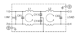
An EMC filter uses a concept called an X capacitor and Y capacitors along with a coil which neutralizes the magnetic pulses that result from these capacitors doing their job. In this diagram there are 2 X capacitors, one Y capacitor circuit and a pair of coils (called Current Chokes).
It physically looks like the left hand part of this circuit board.
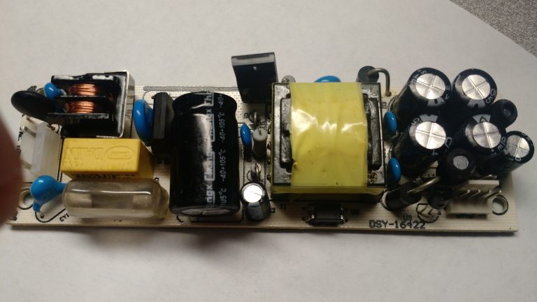
Notice the yellow square part on the left side of the circuit board which is the Y capacitor and the two little blue parts nearby which are the two X capacitors and the part that has the shiny copper looking set of wires, that is the “Current Choke” and there are two of them in the same component frame. Everything to the right of these parts are the switching part of the power supply and its supporting other parts
For those unfamiliar with electronics let me explain the diagram above. #1 and #2 is the input 240 Volts AC voltage coming into the circuit. #3 and #4 are the 12 Volts output DC of the power supply that would connect to power the other electronics. R1 is a small resistor which helps to clip the peak of the oscillations while the CX1 capacitor does its job of removing the larger peak of the oscillations. L1 represents what is called a current choke (a type of transformer coil) which neutralizes the magnetic field via current flow created by CX1 when it clips the oscillations to the opposing side of the AC cycle. That is reflected in the semi circular curve. Please note the AC is cycling from zero to full voltage and flips polarity 60 times a second. So while #1 is at full voltage #2 is at low voltage. This flips back and forth between #1 and # 2 60 times a seconds. The capacitor CX1 targets this high voltage and low voltage condition and the flipping of this high to low condition in order to do its job. CX2 does the same thing and it catches any remaining high transients after CX1 does its job.
Then you will also note the Y capacitors CY3 and CY4 which work in a similar fashion only instead of neutralizing one side of the high voltage to the low voltage side of the 60 cycle voltage change, it neutralizes the remaining transients to ground, as reflected by the symbol that looks like an upside down Christmas tree. L2 is another current choke coil to eliminate the remaining current created by the Y capacitors. The Y capacitor relies on a connection to ground, which is not present in all Smart Meters on the market. So to fix the Smart Meter would require a complete redesign of the power supply circuit board.
There only two options for a consumer to use to avoid all these effects. One is to revert back to an electromechanical meter (Analog Meter) that we have had on our homes for the last 80 years with no internal electronics or to install a parasitic EMC filter that cost much less that an inline current carrying EMC filter, but will still cost about $1,000 to obtain.
I have included here some links here on studies that document the known health effects of bad EMC.
Have your electric bills increased dramatically? If so check this out.
The Presentation that follows along with the testimony.
Here is a video of the Aclara I-210+C meter Oscilloscope Trace done in March 2018
The presentation I did on the Aclara I-210+C meter.
Check out this blog for reference studies.
http://www.rfreduce.com/robertsblog/Also check these studies.
Sign up for weekly news
DISCLAIMER NOTICE OF RESULTS YOU MAY HAVE, FINANCIAL DISCLOSURE, GENERAL DISCLAIMER, PRIVACY STATEMENT
DISCLAIMER NOTICE OF RESULTS YOU MAY HAVE In the text of this web page/site there may be descriptions of results, achievements or accomplishments of one nature or another that an individual or other entity could possibly realize.
The Publisher does not warrant, represent or suggest in any way, that these results, achievements or accomplishments can be expected to be realized, by any person or other entity. The results, achievements or accomplishments that may be discussed on this web page/site are not to be interpreted as average, typical or expected. The results, achievements or accomplishments of any person or other entity could be more, less, the same or there may be no results, achievements or accomplishments at all.
FINANCIAL DISCLOSURE
This web page and this web site may have hyperlinks contained within them, that will result in fee being paid to the Publisher if you click on them.
This web page and this web site may have hyperlinks contained within them, that if clicked, will take you to a sales page or sales presentation, where if you decide to purchase the product or service that is presented, the Publisher may possibly earn a commission.
GENERAL DISCLAIMER
This website is provided “as is” without any representations or warranties, express or implied. The Publisher makes no representations or warranties in relation to this web page/site or the information and materials provided on this web page/site.
Without prejudice to the generality of the foregoing paragraph, the Publisher does not warrant that:
– this web page/site will be constantly available, or available at all; or – the information on this web page/site is complete, true, accurate or non-misleading.
Nothing on this web page/site constitutes, or is meant to constitute, advice of any kind. If you require advice in relation to any legal, financial, medical or other matter you should consult an appropriate professional. This web page/site is intended for entertainment purposes only.
PRIVACY STATEMENT
Your privacy is important to the Publisher. This privacy statement provides information about the personal information that the Publisher collects, and the ways in which the Publisher uses that personal information.
Your Personal Information Is Strictly Guarded. The Publisher does not rent, sell, share, loan, barter or in any way disclose your personal information to any person or organization outside of the Publisher’s company.
Personal information
The Publisher may collect and use the following kinds of personal information:
– information about your use of this web page/site such as the pages that you visit – information that you provide using for the purpose of registering with the web page/site such as your opting into a mailing list and providing your email address – any other information that you send to the Publisher such as entering a ticket into the Publisher’s help desk system
Securing your data
The Publisher will take reasonable technical and organizational precautions to prevent the loss, misuse or alteration of your personal information.
The Publisher will store all the personal information you provide on its secure servers.
Other websites
This web page/site contains links to other websites.
The Publisher is not responsible for the privacy policies or practices of any third party.
Publisher Information: Midwest Research Corp. (M.R. Corp.) P.O Box 2256 Fairfield, IA 52556 USA
This web page/site disclaimer is based, in part, on a precedent created by template-contracts.co.uk and published by freenetlaw.com